Division, continued. Sheet 3 of 12.
Multiplication, continued. Sheet 2 of 4.
Approximative division, continued. Sheet 11 of 12.
Approximative division, continued. Sheet 9 of 12.
Approximative division, continued. Sheet 5 of 12.
Approximative division, continued. Sheet 6 of 12.
Verticals for approximative division. Sheet 3 of 4.
Selectors, drawings 82 and 83, using. Sheet 3 of 4.
Sketches of various notations.
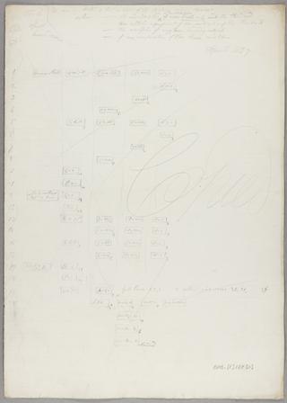
Cases of common and approximative multiplication and their corresponding variations introduced.
Counting the digits in any variable P or in any number of variables P Q R et cetera.
Vertical positions of the wheels of Plan 28. Sheet 12 of 23.
Multiplication.
Algebraic addition of i k figures. Sheet 7 of 8.
Algebraic addition of i k figures. Sheet 5 of 8.
Algebraic addition of i k figures. Sheet 4 of 8.
Algebraic addition of i k figures by the method described in Sketch Book Vol IV p 95 and with General Plan 28. Sheet 1 of 8.
Untitled. [Trains and vertical motions of the wheels and axes of the right, middle and left groups of Plan 28a for division as performed in working Notation 290]. Sheet 4of 4.
Verticals for algebraic addition of k figures.
Trains and vertical motions of the wheels and axes of the right, middle and left groups of Plan 28a for division as performed in working Notation 290. Sheet 1 of 4.
Algebraic addition. Sheet 2 of 2.
Vertical motions for algebraic addition of i k figures. Sheet 2 of 2.
Motions of some of the axes.
Vertical motions of the wheels and axes of the centre group. Sheet 4 of 4.
Lockings of Plan 28a.
Trains and vertical motions of the wheels and axes of the table group of Plan 28a for algebraic addition, as performed in working Notations 306 and 321.
Notation 348 cycle 19. Sheet 3 of 13.
Notation 348 cycle 18. Sheet 2 of 13.
Untitled. [Vertical motions for multiplication and division]. Sheet 2 of 5.
Notation 331 cycles 21 and 26. Sheet 9 of 13.
Notation 348 cycle 26. Sheet 8 of 13.
Untitled. [Vertical positions of some of the wheels of Plan 28a. Notation 348 and 331 cycles]. Sheet 13 of 13.
Untitled. [Vertical positions of some of the wheels of Plan 28a. Notation 348 and 331 cycles]. Sheet 12 of 13.
Notation 348 cycle 26. Sheet 6 of 13.
Notation 348 cycles 26 and 27. Sheet 5 of 13.
Notation 348 cycle 20. Sheet 4 of 13.
Notation of units for various methods of giving motion to Difference Engine No. 2. Sheet 2 of 2.
Notation of units for Difference Engine No. 2. Sheet 1 of 2
General trains. Circular motion of axes.
Times of action.
List of the combinations in division performed as in Notation 290, with the cycles in which they occur. Sheet 1 of 4.
Mill counting apparatus. Vertical motions of the axes ordered by barrel no. 2. Sheet 4 of 5.
Skeleton of vertical motions for all operations. Right groups. Multiplication and division from 372 Sheet 1. Sheet 1 of 3.
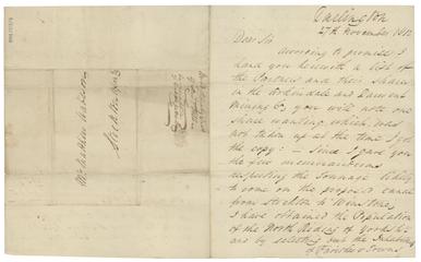
Letter from Robert Botcherby, Darlington to Matthew Madeson, Stockton
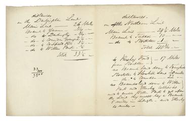
Comparative statement of distances of the south and north lines proposed
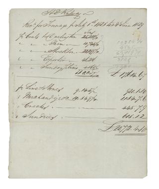
Receipt for tonnages hauled on the Stockton and Darlington Railway

Note regarding payment of £18.0.0 on the Sugar House mortgage from J S Raisbeck to Cuthbert Burrell

Receipt from J S Raisbeck & Co to George Hutchinson for £8.14.3
